Gas lift is perhaps the most widely used of all the Artificial Lift Methods. It is a lift method that is known for its extreme flexibility in providing solutions to various well-bore hydraulic problems and in most cases, it is durable throughout the life span of the well. It is however not without its own
operational problems; the most severe of which are:
An initial design error in the placement of lift mandrels or a design which fails to account for current and future characteristics of the well-reservoir system. Accuracy and optimized gaslift design if required during initial well design.
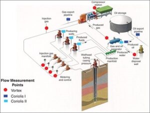
Continuing availability of adequate volume of high-pressure-gas source for injection and the ability to maintain an optimum, stable gas injection rate into each of the wells in a multi-well reservoir.at the later stage of the reservoir life cycle. Compressor often required, where high gas pressure is available, it is practicable and economical to go best practice and take gas direct to well manifold without high capital investment on compressors.
- Inability to accurately measure all the fluid components (oil, water and gas) in the fluid flow stream using the two pen chart system; and particularly our inability to resolve the measurement nightmare traditionally associated with the common but irregular, turbulent multiphase flow regimes in pipes.
- Where source of gaslift gas is high pressure gas well(s), the gas must be controlled to a specified, desired pressure. The gas must be conditioned (dried, where possible etc.) to a specified quality.
The volume of gas must be sufficient to provide for gas-lift requirements, recognizing that these requirements will likely grow over time. Keep in mind that use of 4-rate optimisation test will be required because limited control system in this case.
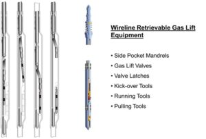
The mechanism of gas-lifting is fairly straightforward. It involves injecting high-pressure gas through the annulus into the tubing through the gas-lift integral mandrel valves located at prescribed depths downwards to the lowest point possible. As the gas flows upwards through the tubing to the surface, it expands, reducing the average fluid density and the weight of the fluid column inside the tubing. The reduction of the fluid column weight enables the low formation pressure to push up the low density fluid column for production through the tubing. Furthermore, the fluid column weight reduction also manifest itself as an equivalent reduction in the well-bore flowing bottom-hole tubing pressure, causing an increase in pressure differential across the sand face and a consequent increase in oil production from the reservoir. In theory therefore, gas-lift performance is based on the balance of forces between improved buoyancy in the tubing string and the corresponding increase in the flowline back-pressure of the multi-phase flow stream.
Normally oil production increases as gas injection rate increases. However the gas injection rate has an optimum limit beyond which we enter the elusion phase during which a high rate of gas injection will cause slippage as the gas phase moves faster than the liquid phase.
Generally, three central issues are key to a successful gas lift injection optimization program. The
issues are:
- Inability to maintain constant gas injection rate at the gas-lift injection header as a result of inadequate availability of requisite compressed gas, and/or inadequate compressor capacity or frequent compressor down time or poor gas wells performance.
- Poor implementation of a purpose designed well-head surveillance program to ascertain real time performance of gas-lifted wells.
- Inadequate four rate gaslift optimisation to ensure optimum gaslift injection and
- Poor compliance to timely optimization well tests required to re-calibrate the production model needed to construct the performance profiles of wells under gas-lift.
Deployment and Valves


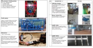
GASLIFT EQUIPMENT WITH PICTURES


